> ## Documentation Index
> Fetch the complete documentation index at: https://docs.intrusiverobotics.com/llms.txt
> Use this file to discover all available pages before exploring further.
# Hardware pinouts
> Connector and pad reference for the Delta GaN ESC — servo/PPM, CAN, UART, USB-C, phase pads, and power terminals.
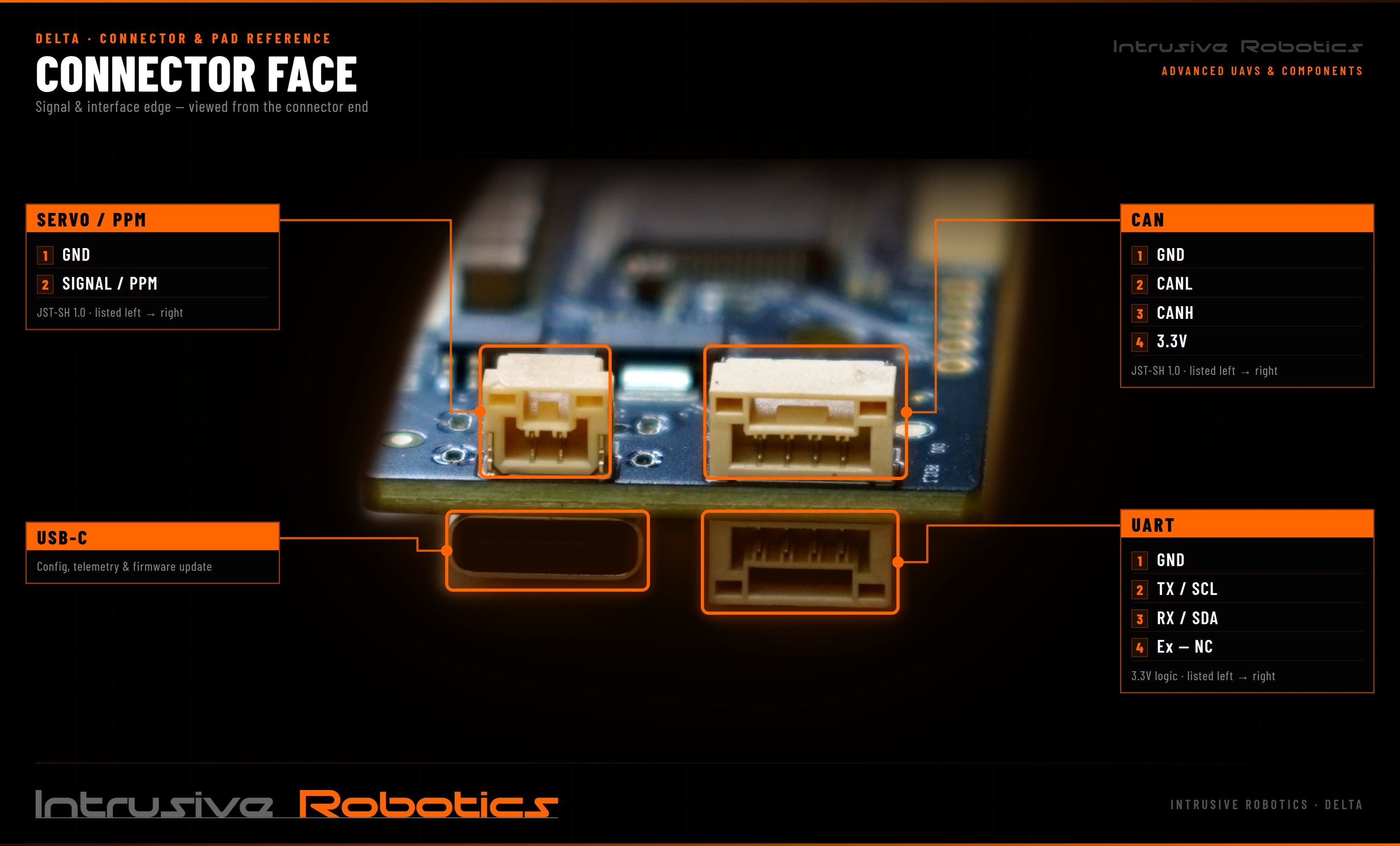
Connector and pad reference for the Delta GaN ESC. All four interfaces — servo/PPM, CAN, UART, and USB-C — sit on the same edge of the board.
**Check the pin order against the board before wiring.** Signal order reverses depending on which side you view the connector from — match the sequence to the matching view below, and confirm against the silkscreen with the board in front of you.
## Board views
 ## Signal connectors
### Servo / PPM
2-pin JST-SH 1.0. This is the PPM input configured in [input configuration](/guides/input-configuration).
| View | Direction | Order |
| -------------- | ------------ | ----------------- |
| Connector face | left → right | GND, SIGNAL / PPM |
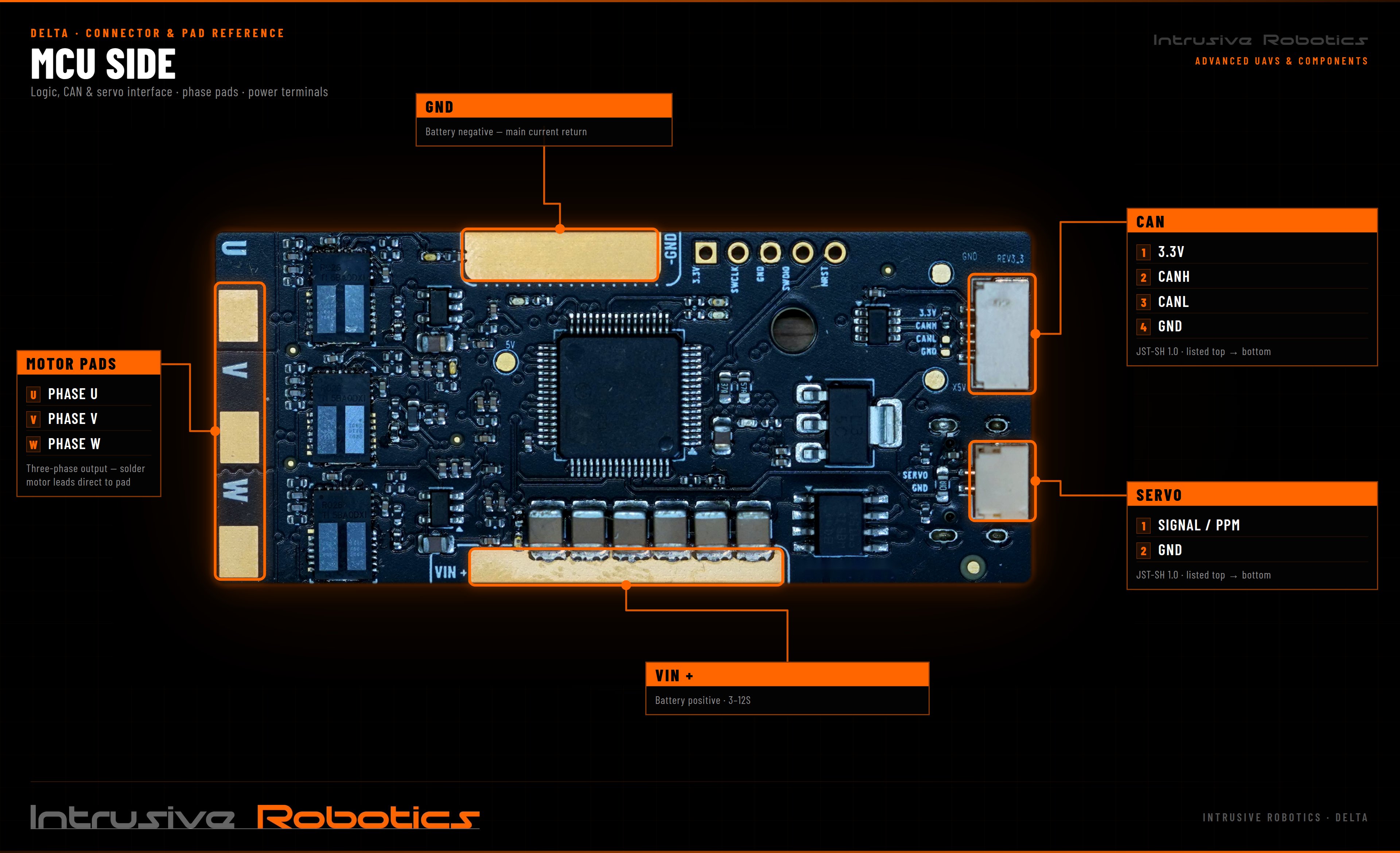
| MCU side | top → bottom | SIGNAL / PPM, GND |
### CAN
4-pin JST-SH 1.0. Used for [UAVCAN / DroneCAN](/guides/uavcan) and VESC-native CAN.
| View | Direction | Order |
| -------------- | ------------ | ---------------------- |
| Connector face | left → right | GND, CANL, CANH, 3.3 V |
| MCU side | top → bottom | 3.3 V, CANH, CANL, GND |
**Wire only GND, CANH, and CANL. Leave the 3.3 V pin unconnected.**
This is the recommended way to connect the Delta to a CAN bus. The 3.3 V pin is not intended to power external devices — see [auxiliary power](#auxiliary-power) — and connecting it to a device that supplies its own rail ties two supplies together.
### UART
4-pin, **3.3 V logic**.
| View | Direction | Order |
| -------------- | ------------ | -------------------------------- |
| Connector face | left → right | GND, TX / SCL, RX / SDA, Ex — NC |
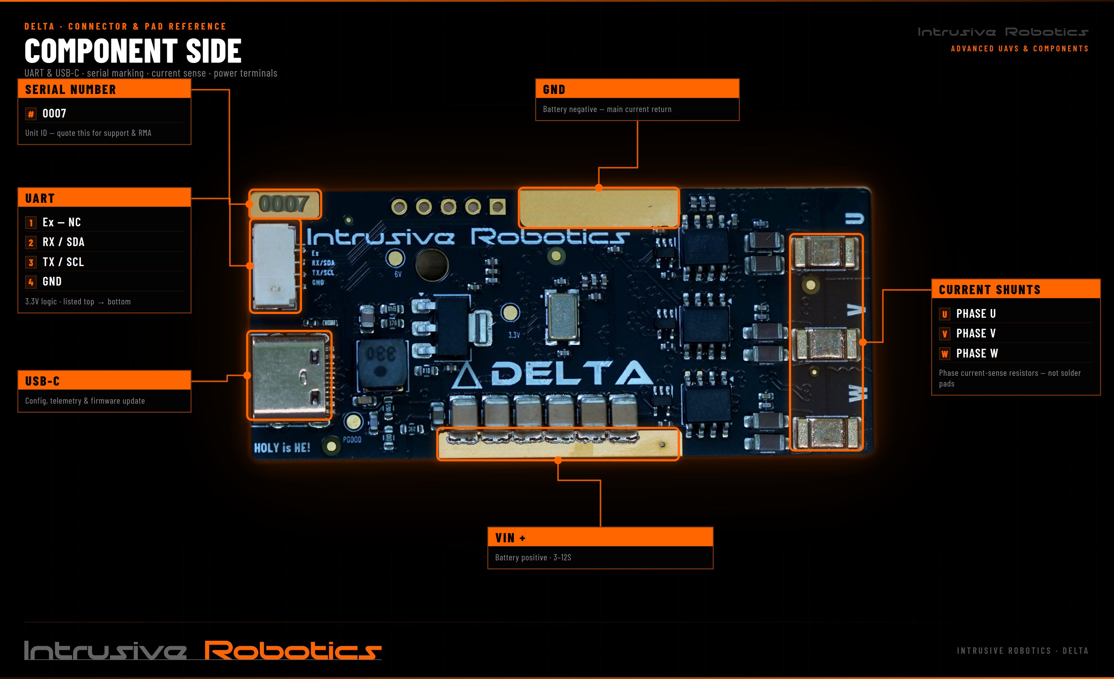
| Component side | top → bottom | Ex — NC, RX / SDA, TX / SCL, GND |
The data pins are **shared between UART and I2C** — TX doubles as SCL, RX as SDA. Which function is active depends on firmware configuration; the pins cannot serve both at once.
`Ex` is not connected.
UART is **3.3 V logic**. Do not connect a 5 V device directly without level shifting.
### USB-C
Configuration, telemetry, and firmware update.
**USB is data only — the Delta is not powered over USB.** It will not boot or enumerate until DC power is applied to the main terminals. Use a USB A → USB C cable. See the [quickstart](/guides/quickstart).
## Power and phase
High voltage and high current. Up to **93 V continuous** input and **70 A continuous** output with forced airflow. Never make or break these connections under load, and use an anti-spark connector on the battery side.
| Pad | Signal | Location | Notes |
| --------- | ---------------- | ---------- | -------------------------------- |
| **VIN +** | Battery positive | Both sides | 3–12S |
| **GND** | Battery negative | Both sides | Main current return |
| **U** | Phase U | MCU side | Solder motor leads direct to pad |
| **V** | Phase V | MCU side | Solder motor leads direct to pad |
| **W** | Phase W | MCU side | Solder motor leads direct to pad |
**Solder motor leads to the phase pads on the MCU side only.**
The U / V / W features in the corresponding position on the **component side are the phase current shunts, not solder pads.** Do not solder motor leads to them.
Phase order determines direction of rotation. Prefer flipping the direction toggle in Motor Settings over swapping phase leads — see [motor tuning](/guides/motor-tuning).
## Auxiliary power
The Delta's low-voltage rails are sized for the controller's own logic and gate drive. They are not a general-purpose supply, and auxiliary capacity is limited.
**Do not power external devices through the board.** Receivers, companion computers, servos, lights, and any other load should be powered from their own supply, not from the Delta.
Anything drawn from the board's rails comes out of the budget the controller needs to run.
Browning out the low-voltage rail takes the controller's logic down with it. On a moving vehicle that means losing motor control.
## Serial number
Each board carries a unit ID on the component side, next to the UART connector (for example `0007`). **Quote this for support and RMA.**
### NDAA compliance
Serial numbers prefixed with **`N`** — for example `N0007` — identify **NDAA-compliant** boards.
If NDAA compliance is a requirement for your programme, check the prefix on the physical board. The marking on the unit is the authoritative record.
## Not yet documented
| Item | Status |
| ------------------------------------- | --------------------------------------------------------------------- |
| CAN bus termination | Not specified |
| Board dimensions and mounting pattern | Not specified |
| Debug / programming header | A pad row is present on the MCU side; assignments not documented here |
## Related
PPM, ADC, UART, and CAN control sources.
Running the Delta as a UAVCAN ESC node.
## Signal connectors
### Servo / PPM
2-pin JST-SH 1.0. This is the PPM input configured in [input configuration](/guides/input-configuration).
| View | Direction | Order |
| -------------- | ------------ | ----------------- |
| Connector face | left → right | GND, SIGNAL / PPM |
| MCU side | top → bottom | SIGNAL / PPM, GND |
### CAN
4-pin JST-SH 1.0. Used for [UAVCAN / DroneCAN](/guides/uavcan) and VESC-native CAN.
| View | Direction | Order |
| -------------- | ------------ | ---------------------- |
| Connector face | left → right | GND, CANL, CANH, 3.3 V |
| MCU side | top → bottom | 3.3 V, CANH, CANL, GND |
**Wire only GND, CANH, and CANL. Leave the 3.3 V pin unconnected.**
This is the recommended way to connect the Delta to a CAN bus. The 3.3 V pin is not intended to power external devices — see [auxiliary power](#auxiliary-power) — and connecting it to a device that supplies its own rail ties two supplies together.
### UART
4-pin, **3.3 V logic**.
| View | Direction | Order |
| -------------- | ------------ | -------------------------------- |
| Connector face | left → right | GND, TX / SCL, RX / SDA, Ex — NC |
| Component side | top → bottom | Ex — NC, RX / SDA, TX / SCL, GND |
The data pins are **shared between UART and I2C** — TX doubles as SCL, RX as SDA. Which function is active depends on firmware configuration; the pins cannot serve both at once.
`Ex` is not connected.
UART is **3.3 V logic**. Do not connect a 5 V device directly without level shifting.
### USB-C
Configuration, telemetry, and firmware update.
**USB is data only — the Delta is not powered over USB.** It will not boot or enumerate until DC power is applied to the main terminals. Use a USB A → USB C cable. See the [quickstart](/guides/quickstart).
## Power and phase
High voltage and high current. Up to **93 V continuous** input and **70 A continuous** output with forced airflow. Never make or break these connections under load, and use an anti-spark connector on the battery side.
| Pad | Signal | Location | Notes |
| --------- | ---------------- | ---------- | -------------------------------- |
| **VIN +** | Battery positive | Both sides | 3–12S |
| **GND** | Battery negative | Both sides | Main current return |
| **U** | Phase U | MCU side | Solder motor leads direct to pad |
| **V** | Phase V | MCU side | Solder motor leads direct to pad |
| **W** | Phase W | MCU side | Solder motor leads direct to pad |
**Solder motor leads to the phase pads on the MCU side only.**
The U / V / W features in the corresponding position on the **component side are the phase current shunts, not solder pads.** Do not solder motor leads to them.
Phase order determines direction of rotation. Prefer flipping the direction toggle in Motor Settings over swapping phase leads — see [motor tuning](/guides/motor-tuning).
## Auxiliary power
The Delta's low-voltage rails are sized for the controller's own logic and gate drive. They are not a general-purpose supply, and auxiliary capacity is limited.
**Do not power external devices through the board.** Receivers, companion computers, servos, lights, and any other load should be powered from their own supply, not from the Delta.
Anything drawn from the board's rails comes out of the budget the controller needs to run.
Browning out the low-voltage rail takes the controller's logic down with it. On a moving vehicle that means losing motor control.
## Serial number
Each board carries a unit ID on the component side, next to the UART connector (for example `0007`). **Quote this for support and RMA.**
### NDAA compliance
Serial numbers prefixed with **`N`** — for example `N0007` — identify **NDAA-compliant** boards.
If NDAA compliance is a requirement for your programme, check the prefix on the physical board. The marking on the unit is the authoritative record.
## Not yet documented
| Item | Status |
| ------------------------------------- | --------------------------------------------------------------------- |
| CAN bus termination | Not specified |
| Board dimensions and mounting pattern | Not specified |
| Debug / programming header | A pad row is present on the MCU side; assignments not documented here |
## Related
PPM, ADC, UART, and CAN control sources.
Running the Delta as a UAVCAN ESC node.